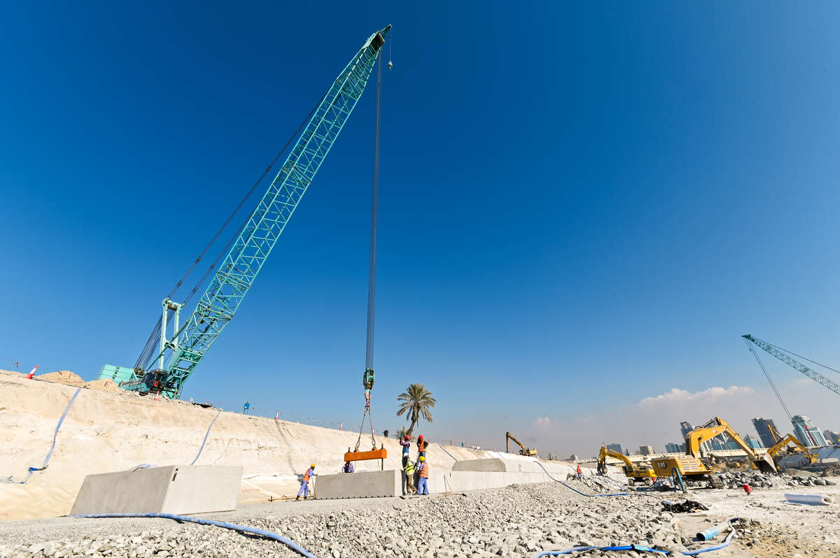
A crawler crane is one of the most capable lifting machines available — high capacity, excellent stability, and the rare ability to travel with a suspended load. It is also unforgiving. A crawler crane failure is rarely a minor incident, and almost every recorded collapse traces back to something decided before the hook ever moved: ground conditions, configuration, load chart interpretation, or a lift that was never properly planned. This guide covers crawler crane components, assembly, load charts, lifting technique, travel, and the safety framework that governs the work.
What Is a Crawler Crane and How Does It Work
A crawler crane is a lattice-boom or telescopic-boom lifting machine mounted on a tracked undercarriage. Unlike a mobile crane, it does not deploy outriggers — the tracks themselves provide the support base, spreading weight over a much larger footprint. That gives a crawler crane two defining advantages: it can work on softer ground than a wheeled crane of equivalent capacity, and it can pick and carry, moving a suspended load across a site within the limits set by the manufacturer.
The trade-off is mobility between sites. Crawler cranes cannot travel on public roads. They are dismantled, transported in components, and reassembled on site, which means every deployment carries assembly time and cost that a mobile crane does not.
Crawler cranes fall within the scope of ASME B30.5, the safety standard covering mobile and locomotive cranes, which addresses construction, inspection, testing, maintenance, and operation.[1]
Crawler Crane Components and Structure
- The undercarriage (crawler assembly) consists of two track frames, travel motors, drive sprockets, idlers, track rollers, and track shoes. Track width and length determine ground contact area, which directly determines ground bearing pressure. On large machines the crawler side frames are removable for transport and the car body carries central counterweight.
- The car body is the structural link between the two crawler frames, carrying the slew bearing on which the upper works rotate.
- The upper works (superstructure) carries the engine, hoist drums, boom hoist mechanism, slew drive, cab, and rear counterweight. On heavy-lift configurations, additional counterweight may sit on a separate trailing tray or a superlift assembly on its own wheels.
- The boom is typically a lattice structure assembled from a base section, insert sections, and a top section. Configurations vary widely: main boom only, main boom with fixed jib, or main boom with luffing jib, which allows the tip to move independently of the main boom angle and is common for tight, tall lifts.
- The reeving and load-handling system comprises main and auxiliary hoist drums, wire rope, sheaves at the boom head, hook block, and the boom hoist rope or hydraulic cylinder. Falls of line — the number of rope parts supporting the hook block — determine maximum line pull capacity independently of the crane’s structural rating.
Crawler Crane Operator Certification and Competency
Crawler crane operation requires formal certification everywhere it is commercially performed. ASME B30.5 specifies operator qualification requirements and, since the 2018 edition, also defines the role of the qualified rigger — requiring a qualified rigger to be present for lifting operations.[2]
Certification is machine-class specific. A card covering telescopic mobile cranes does not authorise lattice-boom crawler operation, because the assembly procedures, load chart structure, and stability behaviour are materially different. Practical assessment on the crane class you intend to operate is the standard requirement.
The operator is also not the only certified role on the lift. A compliant lifting operation involves an appointed person or lift planner who produces the lift plan, a lift supervisor, a qualified rigger, and a designated signalperson. Understanding where your authority ends is part of operating competence — if the lift plan does not match what is in front of you, the correct action is to stop, not to improvise.
Site Preparation and Ground Bearing Pressure
This is where most crawler crane incidents originate, and it deserves more attention than the controls do.
Crawler cranes spread load along two tracks over a large area, but the loads involved are still substantial and can shift heavily toward one side during a pick, so the ground under the tracks must be assessed rather than assumed.[3] Ground bearing pressure is the pressure the machine exerts through its support points, and it is not simply total weight divided by four — the loading varies dramatically with boom position, load weight, and operating radius, with the support closest to the load carrying substantially more force.[4]
Ground bearing pressure is calculated as total load — crane weight plus counterweight plus rigging plus the lifted load — divided by track contact area. As a broad screening guide, pressures below roughly 100 kN/m² are generally manageable on compact ground; 100–200 kN/m² usually calls for ground improvement or crane mats; and above 200 kN/m² a detailed geotechnical assessment with engineered mats is appropriate.[5] These are screening values, not a substitute for site-specific data. Without a geotechnical report, soil testing, or at minimum an assessment by a competent person, you are estimating — and estimating ground conditions has caused a long list of crane accidents.[4]
What matters practically on site:
- Peak pressure is not average pressure. With the boom over the front at minimum radius, much of the track length is engaged. As the boom swings and the radius extends, load concentrates toward one corner of the track. Peak track pressures for a 200-tonne class machine in main boom configuration can reach the region of 25 t/m² in certain configurations — a value that may be unacceptable on an ordinary site road.[6]
- Mats must be engineered, not improvised. Timber mats need shear strength, bearing capacity, and bending strength checked for the material and thickness in use — excessive shear stress cracks timber, which sharply reduces bending resistance and invites failure. Loads should also be placed toward the centre of a mat, away from the edges.[7]
- Check what is under the surface. Backfilled trenches, basements, culverts, service ducts, and buried tanks can all be invisible from ground level and will not support a track corner.
- Confirm slope. Most manufacturers restrict operation to a very small gradient — often around 1% for lifting duties — and travelling limits are separately specified.
Crawler Crane Assembly and Rigging Up
Assembly is a lifting operation in its own right, planned in as much detail as the lifts that follow, and carried out under the manufacturer’s procedure with an assist crane.
The typical sequence: the car body and crawler frames are positioned and pinned, tracks are connected and tensioned, central counterweight is installed, the upper works is set on the slew bearing, rear counterweight is stacked and secured, boom sections are laid out and pinned in the correct order, reeving is run, and the boom is raised from the ground under controlled boom-hoist tension.
Several points recur in assembly incidents:
- Pin retention. Every boom connection pin needs its retaining device fitted and verified. This is checked by a second person, not just the fitter.
- Section order. Lattice inserts are not interchangeable. Sections are rated and tapered, and installing them out of the specified order alters the boom’s structural capacity. Verify section identification numbers against the configuration drawing.
- Counterweight matching. The counterweight fitted must exactly match the configuration in the load chart being used. Running a chart that assumes 80 tonnes of counterweight with 60 tonnes fitted is a direct route to tipping.
- Boom raising. The moment of highest stress on a lattice boom is often during initial raising from horizontal, when the boom is at a shallow angle and bending moments peak. Wind during boom raising is a serious hazard and this operation should be avoided in gusty conditions.
- Post-assembly verification. Before the first lift, confirm reeving is correct and rope is properly seated in sheaves, verify the anti-two-block system triggers, test the load moment indicator against a known weight where practicable, and check all limit switches.
- Reading the Crawler Crane Load Chart
- The load chart is the operating envelope, and misreading it is the most common cause of overload.
- Rated capacity depends on radius, not boom length alone. Radius is measured from the centre of rotation to the centre of the load, horizontally. As the load swings out, radius increases and capacity drops sharply — not linearly.
- Deductions are the operator’s responsibility. Published capacity is gross. The hook block, wire rope weight, slings, shackles, spreader beams, lifting frames, and any jib fitted all subtract from it. On a long-boom lift the rope weight alone can be significant. Net capacity is what remains after every deduction.
- Charts are configuration-specific. Boom length, jib length and offset, counterweight arrangement, track extension position (retracted or fully extended), and number of parts of line each define which chart applies. A crawler crane may have dozens of charts in the manual; using the wrong one is functionally identical to having no chart.
- Quadrant of operation matters. Unlike an outrigger-supported crane, a crawler crane’s capacity varies with slew position relative to the tracks. Over-the-side capacity is generally the most restrictive; over-the-front and over-the-rear differ. Some manufacturers publish a single 360° chart, others publish quadrant-specific values — know which you are reading.
- Structural versus stability limits. At short radius, capacity is limited by the strength of the boom and structure. At long radius, it is limited by tipping. Charts often mark the transition point, and the load moment indicator behaves differently on either side of it.
- Percentage-of-tipping. Crawler crane charts are typically published at 75% of tipping load for on-crawler operation, though this varies by standard and manufacturer. That margin is not spare capacity to be spent.
Pre-Operational Inspection Checklist
Before each shift, working from the ground up:
- Undercarriage. Track tension, condition of shoes and pins, sprocket and idler wear, travel motor and final drive leaks, and confirmation that tracks are properly pinned in their extended or retracted position matching the chart in use.
- Structure. Boom chords and lacings inspected for dents, bows, cracks, or corrosion — a dented lattice chord is a compression member with reduced buckling capacity and grounds for taking the crane out of service. Check all pins and retainers, and inspect the boom hoist system.
- Wire rope. Inspect for broken wires, crushing, birdcaging, kinking, corrosion, and reduction in diameter. Rope inspection criteria are defined in ASME B30.5 and rope should be replaced against those criteria rather than by judgement.[1]
- Hook and rigging. Check the hook for throat opening increase, twist, cracks, and wear at the saddle. Confirm the safety latch operates. Inspect slings and shackles.
- Safety devices. Verify anti-two-block, load moment indicator, boom angle indicator, boom hoist limit, hoist drum rotation indicator, and level indicator. Confirm the horn, lights, and fire extinguisher.
- Fluids and drivetrain. Engine oil, coolant, hydraulic level, fuel, and any visible leaks. Check brake and clutch function on the hoist drums.
Log the inspection. On a crane, the inspection record is a legal document as much as a maintenance one.
Crawler Crane Controls and Operating Technique
Cab layout varies by manufacturer, but the functional set is consistent: two joysticks or lever banks controlling main hoist, auxiliary hoist, boom hoist (or luffing), and slew; foot pedals for swing brake and travel; and separate travel levers or pedals for the left and right tracks.
- Start up with the engine at low idle, allow hydraulic oil to warm before applying load, and cycle each function unloaded through its range while watching for drift or abnormal noise.
- Hoisting. Take up slack slowly and pause with the load just clear of the ground. This is the critical checkpoint of any lift: confirm the load is stable, the rigging is seated, the crane is level, the load moment indicator reads as expected, and nothing is snagged. Only then continue lifting.
- Keep the rope vertical. Side loading a lattice boom is one of the fastest ways to destroy one. If the hoist rope is not plumb over the load before lifting, reposition the crane or adjust radius — never drag the load into position with the hoist.
- Slew smoothly. Acceleration and deceleration both induce load swing, and a swinging load increases effective radius beyond the planned figure. Slew slowly, and lead the stop so the load settles rather than pendulums. Use tag lines on any load with meaningful sail area.
- Booming down increases radius. Lowering the boom while holding a load moves the load outward and can walk the crane straight into an overload even though the load has not changed. Boom angle and radius must be watched continuously, not just set at the start.
- Do not rely on the load moment indicator as a working limit. It is a warning device, not a permission system. The lift plan defines what is acceptable; the LMI tells you when you have already gone wrong.
Travelling and Pick-and-Carry Operation
The ability to travel with a load is a crawler crane’s signature capability and also a high-risk operation.
Travelling unloaded: carry the boom low, aligned with the direction of travel, and check the route for slope, soft spots, buried services, and overhead obstructions. Travel at low speed. Remember that travel is referenced to the undercarriage, not the cab — if the upper works has been slewed, “forward” on the travel controls moves the machine relative to the tracks, not relative to where you are facing.
Travelling with a suspended load requires that the manufacturer explicitly permits it in the configuration in use, and always at a reduced capacity from the static chart. Additional controls apply: keep the load as low as practicable, keep the boom over the front or in the specified quadrant, use tag lines, travel only over a prepared and level route that has been assessed for the dynamic loading, and move at walking pace with a banksman. Any change in gradient or any sudden stop induces load swing and dynamic loads that the static chart does not account for.
Wind Limits and Adverse Weather
Wind is the environmental factor most likely to end a lift. Crawler cranes, despite their stable base, are sensitive to gusts because of their large exposed surface area, and a commonly cited threshold for suspending operations is around 43 km/h (about 27 mph).[8] Published figures generally place crawler crane limits in the region of 26–27 mph, with mobile cranes lower at 20–22 mph.[9]
Those numbers are starting points, not the decision. What actually governs:
Wind acts on the sail area of a load more than on its weight, so large, flat, or lightweight components can become unmanageable well within the crane’s published wind limit. For loads with significant sail area, reduce the operating wind limit by 5–10 mph below the crane’s maximum.[9] One widely used manufacturer guideline is behavioural rather than numerical: if wind moves the centreline of a freely suspended load out past the boom or jib hinge pin on either side, the load should be lowered to the ground immediately and work suspended until conditions improve.[10]
Wind from behind the crane changes the working radius; wind from the side affects boom verticality. Between tall structures, expect wind tunnel effects — swirling and locally elevated speeds that a general site forecast will not show.[11] Measure wind at boom tip height where possible, since ground-level readings understate conditions aloft.
The manufacturer’s manual overrides all general guidance, and the operator’s judgement overrides the manufacturer’s number when conditions on the day warrant it.
Common Crawler Crane Operating Mistakes
- Using the wrong load chart. Configuration mismatches — counterweight, boom length, jib, track position, parts of line — are the leading cause of overload.
- Failing to deduct rigging weight. Reading gross capacity and lifting to it, forgetting the block, rope, spreader beam, and slings.
- Side loading the boom. Dragging loads laterally, or slewing to pull a load that is not directly beneath the boom head.
- Ignoring dynamic loading. Snatching a load, sudden stops, and shock loading all generate forces well above the static weight. Free-fall on the hoist near a load is dangerous for exactly this reason.
- Lifting an unknown weight. “It looks like about three tonnes” is not a load weight. Verify from documentation, weigh it, or use a load cell.
- Working over live areas. Never slew a load over occupied space, live traffic routes, or occupied structures. Establish and enforce an exclusion zone under the full slew radius.
- Underestimating power line clearance. Minimum approach distances to energised lines are prescribed by regulation and are larger than most people expect. Boom, jib, load, and rope all count.
- Leaving the crane unsecured. At end of shift, lower the load, set the boom to the specified parked angle or lower it to a rest, apply swing and travel brakes and locks, and secure against the weather forecast — not the current conditions.
Best Practices for Safe Crawler Crane Operation
Plan every lift on paper before it happens. A lift plan should state load weight, rigging weight, radius, boom configuration, chart capacity, utilisation percentage, ground conditions and mat arrangement, exclusion zones, wind limits, and communication method. If any of these is unknown, the lift is not ready.
Hold a pre-lift briefing with everyone involved — operator, rigger, signalperson, supervisor. Confirm signals and confirm the stop authority: anyone can stop a lift, and the stop signal is obeyed from anyone.
Use one designated signalperson, and maintain radio communication with a defined protocol. If you lose sight of the signalperson or lose radio contact, stop.
Keep utilisation sensible. Routinely operating at 90% of chart capacity leaves no margin for a load heavier than documented, wind, or a dynamic input. Planned lifts should generally sit well below the chart limit.
Never modify or bypass a safety device. Disabling an anti-two-block or LMI to “get the lift done” is present in the accident record with grim regularity.
Frequently Asked Questions About Crawler Crane Operation
- What is the main advantage of a crawler crane over a mobile crane? Lower ground bearing pressure through track distribution, higher capacity at long radius in lattice-boom configuration, and the ability to travel with a suspended load when the manufacturer permits it. The trade-off is that crawler cranes cannot travel on roads and must be assembled and dismantled on site.
- Do crawler cranes need outriggers? No. The tracks provide the support base. This is also why ground preparation under the full track footprint matters more than it does for an outrigger-supported machine, where load concentrates at four points.
- How is crawler crane ground bearing pressure calculated? Total load — crane weight, counterweight, rigging, and lifted load — divided by total track contact area.[5] The result is an average; peak pressure under a loaded track corner is considerably higher and is the value that must be compared against allowable soil capacity.
- Can a crawler crane travel with a load? Yes, where the manufacturer explicitly permits it for the configuration in use, at reduced capacity, over a prepared route, at low speed, with tag lines and a banksman. It is never a default permission.
- At what wind speed should crawler crane lifting stop? Commonly cited thresholds sit around 43 km/h (27 mph)[8], with lower limits for loads with large sail area.[9] The manufacturer’s manual for the specific machine and configuration is the governing figure.
- Which standard covers crawler crane operation? ASME B30.5, Mobile and Locomotive Cranes, covers construction, inspection, testing, maintenance, and operation of crawler cranes among other mobile crane types.[1] Regional regulations apply alongside it.
References
- American Society of Mechanical Engineers. B30.5 — Mobile and Locomotive Cranes. https://www.asme.org/codes-standards/find-codes-standards/b30-5-mobile-locomotive-cranes
- “ASME B30.5 Standard Sets Requirements for Mobile Crane Rigger Qualification.” Crane Equipment Guide. https://www.craneequipmentguide.com/article/57615-asme-b305-standard-sets-requirements-for-mobile-crane-rigger-qualification
- “Ground Bearing Pressure and Crane Site Readiness.” Maxim Crane Works, 2026. https://www.maximcrane.com/blog/ground-bearing-pressure-crane-site-readiness/
- “Crane Ground Bearing Pressure: Calculations, Mat Requirements & Site Assessment.” CraneCheck, 2026. https://cranecheck.co/blog/crane-ground-bearing-pressure-calculations
- “Crawler Crane Ground Bearing Pressure Calculator.” ProIndustrialSpecs, 2026. https://proindustrialspecs.com/calculators/crawler-crane-ground-bearing-pressure-calculator/
- “How to Calculate the Necessary Support Under a Crane.” Crane & Transport Briefing. https://www.cranebriefing.com/news/how-to-calculate-the-necessary-support-under-a-crane/8012492.article
- “Guideline for Crane Stability and Ground Pressure.” HSSE World. https://hsseworld.com/guideline-for-crane-stability-and-ground-pressure/
- “Understanding Crane Wind Speed Limits for All Types of Cranes.” Scarlet Tech, 2025. https://scarlet-tech.com/crane-wind-speed-limit/
- “Wind Speed Limits for Crane Operations.” TDS Crane, 2026. https://www.tdscrane.com/post/wind-speed-limits-for-crane-operations
- “Crane Accident and Wind.” Hard Hat Training. https://www.hardhattraining.com/crane-accident-wind/
- “Weathering Heights — Tower Cranes and Wind.” Hard Hat Training. https://www.hardhattraining.com/blog/weathering-heights-tower-cranes-wind